Journal Entry #6: Choosing Motors
It’s been a while since my last post - life and other projects got in the way. But this one has always been sitting in the background waiting for some time to allow me to jump back in. And honestly, these entries have been invaluable in reminding myself of everything that’s been done and decided. I’m feeling very proud of past-me for writing it all down.
At the end of my last blog post I said this one would be about more creative, less mathy stuff. There are actually a few more things I want to iron out, namely which motors and batteries to use, before jumping into aesthetics. I promise the next one will have less math, though!
Requirements
Luckily we already know most of the requirements for the motors and battery. Here’s everything from the previous entries:
Each of the pitch and roll axes needs a motor that can output at least 6.2 N-cm.
The yaw axis requires a motor with a minimum output torque of 13.2N-cm if using a gear/belt ratio of 12
Must have a battery life of at least 4 hours on a full charge
Each motor needs to be a stepper motor
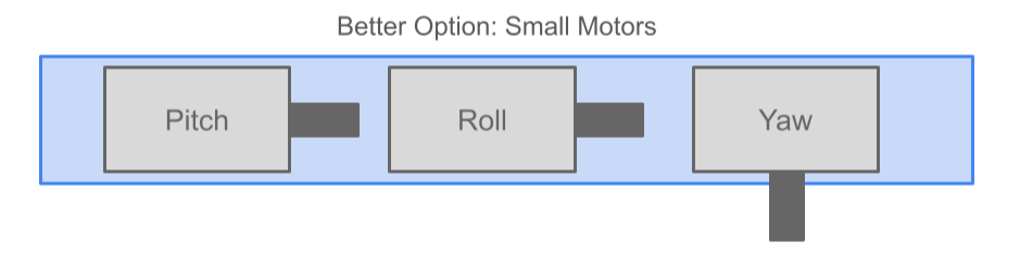
One super easy option that meets and exceeds all these requirements is to use big, strong motors and a big battery to sustain them. To make things more interesting (and cheaper and probably easier to use) I want to try to make the system as flat and thin as possible, so it looks like a platform to put things on instead of a big triangular brick.
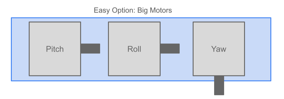
Based on the orientations of the three axes we’ve been designing so far, this will probably mean the pitch and roll motors need to be thin on the sides (since they’ll be lying horizontally) and the yaw motor needs to be short along the axis of rotation (since it’ll be rotating vertically). Hopefully this image explains more effectively:
Battery Power and Electrical Stuff
The power available from the stepper motors depends on a few things:
Voltage supplied
Current supplied
Internal resistance
Inductance (but we can mostly ignore that since the motor will be moving at such slow speeds)
For anyone not familiar with electrical terms, an easier-to-understand analogy of an electrical circuit is just water moving through a pipe. Voltage is the water pressure, current is the water’s flow rate, and resistance is the pipe’s friction or narrowness.
Electrical power is voltage x current, so increasing either one will increase the motor’s power. In the water example if you want to increase the water’s power you can increase the water pressure only (like a power washer), increase the flow rate only (like a river), or both (like a water main pipe).
In our case, the motor (the pipe) will have a constant internal resistance (like a pipe’s narrowness) determined by how the motor was made. This doesn’t change. What we can change are 1. the supplied voltage (water pressure) to the motor and 2. the maximum current we allow the motor to use (the flow rate).
Voltage
The simplest way to get voltage to the motors would be to connect them directly to the battery. We’ll be using the most common type of rechargeable battery, called a LiPo (lithium Polymer) that outputs 3.7V. There are a few problems with this idea, though. First, a LiPo battery’s voltage isn’t constant. Depending on how charged it is, the voltage will change from around 4.2V (at 100% charged) to 3.0V (at 0-10% charged). 3.7V is just the ‘nominal’ or ‘middle’ voltage for the battery. Side note: measuring this changing voltage is the easiest way for a device to tell how charged a LiPo battery is.
The second problem with this direct-to-battery connection is simply that 3.7V is very low. While we could theoretically increase the current to make up for this low voltage, high current causes weird and bad things to happen in electrical circuits (mostly because it causes things to heat up) so it’s a much better idea to increase voltage and decrease current. To increase voltage from the battery, we use an electrical component called a Boost Converter. It takes a voltage input and converts it to a higher (and stable) voltage output at the cost of a lower output current.
There are a few voltage levels that are so commonly used that their respective boost converters are pretty cheap. They include 5V, 9V, 12V, and 24V. We’ll do the math on all of these to see what works best. Once we decide on one voltage level and install the boost converter, though, it can’t be changed. Well, kinda. This voltage level would be the maximum voltage to the motors, but we can use a separate part, called a motor driver, to decrease that voltage to control the motor’s actual strength.
Current and Power
Think of that motor driver as a pressure regulating valve on the water pipe. We tell it how much current (flow rate) we want to go to the motor, and it manipulates the voltage (water pressure) to force the current to that set point. It can only regulate the voltage as high as the maximum set by the boost converter, so it’s a good idea to give it voltage headroom. The relationship between voltage and current depends primarily on the motors’s resistance (the narrowness of the tube)
Remember, power = voltage x current. So if we can figure out how much power we need to give the motor for it to turn with a torque of 6.2N-cm or 13.2 N-cm, we can also calculate the required voltage and current. So let’s do that for a bunch of motors and decide on the best options.
Battery Size
One other thing before we get into the comparisons: Once we know the power that the motors require, we can calculate how big the battery needs to be to output that motor power for the 4 hour requirement. That can be the last thing we calculate, though.
Motor Comparisons - Pitch and Roll
Stepper motors are commonly organized by size into ‘NEMA’ categories. The standard options are NEMA 8, 11, 14, 17, 23, 34, and 42. The larger the number, the bigger the motor. NEMA 17 is by far the most common size, used on most 3D printers, and NEMA 23, 34, and 42 are more often used on CNC machines or industrial equipment. For the pitch and roll motors, I want to compare NEMA 8, 11, and 14. Within these sizes, the motors can range in length and internal electrical specs.
FYI, I’m primarily looking at stepper motors from StepperOnline.com because they’re cheap and usually have a ton in stock.
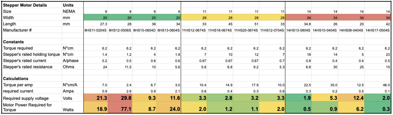
Here’s the comparison. It includes four motors each of NEMA 8, 11, and 14. The two most important numbers to check are the ’required supply voltage’ and the ‘motor power required for torque’. Required supply voltage must be under the maximum voltage we choose for the boost converter (ideally with some headroom) and the motor power required for torque will directly determine how long the motors can run with a given battery size (lower power = longer battery).
A few things stick out to me:
The larger the motor NEMA size (which determines the motor width), the less power it needs to output the required torque.
The NEMA 8 motors typically need a much higher supply voltage for this torque, which makes sense due to their small size.
There are a few outliers, like the 2nd NEMA 8 and the 3rd NEMA 14, that have different internal electrical specifications and require more power or voltage than other motors of their size. We can remove these from consideration.
All in all, this tells me that NEMA 11 might be the sweet spot, and probably the 45mm or 51mm length since they’re twice as efficient as the 33mm versions. These motors are all 28mm wide, which would determine how thick the platform can be. So for the Yaw axis motor , which is perpendicular to these motors, we’ll want the length to be around or less than 28mm.
Verdict: NEMA 11 with 45mm or 51mm length
Motor Comparison - Yaw
We’ll run the same comparison for the yaw axis, but with the required torque set to 13.2 N-cm instead of 6.2:
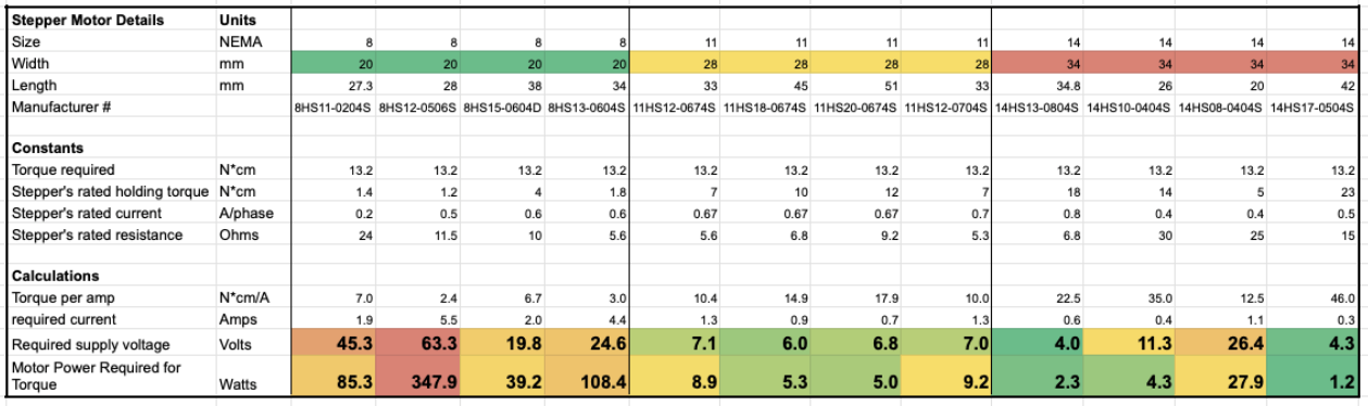
Remember, for this one we want the length to be below 28mm. The NEMA 8 motors require WAY too much power, and none of the NEMA 11 motors are short enough. Let me redo it without those sizes, and adding in some NEMA 17 motors:
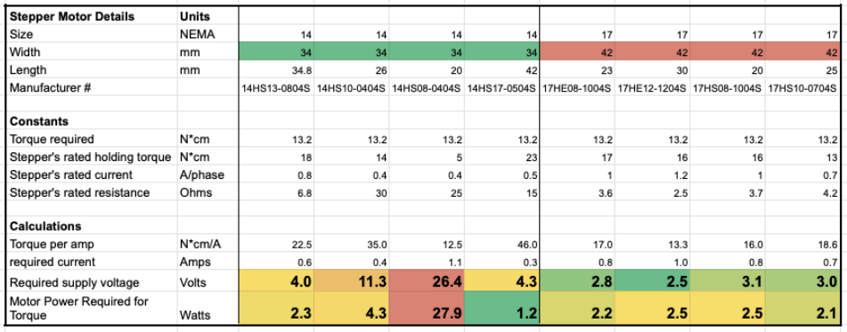
Looks like NEMA 17 is the way to go. All of them would work, but we’ll go with the 25mm variant since it’s the most efficient.
Verdict: NEMA 17 with 25mm length
One More Voltage Thing
We never actually decided on a voltage level for the boost converter. Since the required supply voltage for the pitch and roll motors are 2.8-3.2V and the yaw motor is 3.0V, it’s easy to assume that 5V would be sufficient. However, all these power calculations make one BIG assumption: that the motors will be moving at very slow speeds or just holding still. There will be a few times when we need to motors to move quickly, such as when the system first starts up or when it reaches the end of its range of motion and needs to reset.
At higher speeds, the electrical requirements for a stepper motor get much more complicated. There’s electrical inertia (due to inductance, which in the analogy is the weight of the water in the pipe) and the motor’s back-pressure or back-EMF. At a speed of 300RPM (5 rotations per second) all of this adds up to a required supply voltage of around 8.5V.
Accounting for inefficiencies in the motor driver and some instability in the boost converter’s output, the safe option would be to design around a voltage above 10V. The most commonly used voltage above this level, by far, is 12V. So that’s what we’ll use. Anything higher than that will add conversion losses and stress the components for margin we’d never use.
One quick note: the sensors and processor run on 3.3V, so we’ll need a whole other type of converter for them. We’ll deal with that later.
Battery Size
So when combining these three motors we have a maximum power usage of 2.1+1.2+1.2=4.5 Watts. This is theoretical and very oversimplified. If we include a worst-case boost converter efficiency of 75% (these converters aren’t perfect and lose some energy when converting voltage) and an extra 10% for all the other components (sensors, processors, and UI), we get 6.6W. This is the absolute worst case scenario and isn’t realistic, since the motor drivers will be ensuring the motor is only using the power it needs.
Based on the way we calculated these motor power requirements, I’d be comfortable cutting that power estimate in half.
For pitch and roll we calculated the worst case assuming the individual motor was taking the maximum weight from the user’s telescope, but by definition that means the other motor would have less of the load
For yaw, the worst case assumes the telescope is as far from the center of rotation as possible, the platform is tilted as much as possible, and the yaw axis is in its position of maximum force in its rotation. That position is only reached temporarily, and would be less for the remainder of the 4 hour run time.
So for battery sizing we’ll assume 3.3 Watts (we can always test and revise this later on).
LiPo batteries are typically measured in mAh, or milliamp-hours, which is how many hours they can run a specified current at the battery’s nominal 3.7V.
Current: 3.3 Watts / 3.7V = 0.9 Amps or 891 milliAmps
Multiply that by 4 hours and we get 3568 mAh.
Before we solidify this as the initial battery requirement, there’s one other thing to know about LiPo batteries: they don’t like being charged all the way up or drained all the way down. A safe usable range only allowing it to be charged up to 90% or drained down to 20%, leaving 70% of it usable. That gives us a final value of 5097 mAh, which should be easy to source.
Okay so NOW we can take a break from math! We know which motors will be used and we have a potential battery size, so in the next journal entry we’ll use that info + a lot of other details we’ve already decided upon to start figuring out the shape, size, and aesthetics of the platform.
Thanks for reading!