Journal Entry #5: Error Math!
Just like the previous journal entry about force requirements, this one will be pretty math-heavy. Everything is summarized at the end if you don’t want to read the whole thing, but I will try to keep it pretty high-level all the way through.
This will be split into two sections, one for the pitch and roll axes and another for the yaw axis. Within each section I’ll go over the main mechanical error sources, with an end-goal of determining the absolute worst case error for the system as a whole.
Pitch and Roll Axes
These wedge-based axes have a few notable error sources:
Stepper pulsing/lack of smooth motor control
Inaccuracies in the leadscrew
Error in the machining of the actual angle of the wedge
Flatness of the PTFE strips
Stick-slip from friction causing jerky motion
Stepper Pulsing
As mentioned in a previous entry, stepper motors work by rotating in discrete steps, typically a total of 200 steps in one full rotation. With good control electronics you can get up to ~256 ‘microsteps’, or additional smaller steps between each of those 200 full steps. This sets a maximum of around 50,000 microsteps per rotation.
The error here is due to steps being a bit jerky at low speeds. If you imagine moving slow enough that only one step happens per second, it’ll take that step very quickly and then stay still for the rest of the second. Meanwhile the earth is rotating at a constant smooth speed, so we need to figure out how far the sky might rotate out of alignment between each of these individual steps.
Let’s say we don’t use any microstepping, only the 200 full steps. With the leadscrew and wedge designs mentioned above, this moves the lifter 0.0033mm per step. Based on the distance between lifters in each corner of the platform, this results in one step equaling 0.000204 degrees of platform tilt, or 0.01 arc minute. This equates to the maximum possible error due to stepper pulsing, and it’s basically negligible in our 15 arc minute budget, so micro stepping might not even be necessary.
Leadscrew
The type of leadscrew I have on hand isn’t particularly accurate length-wise. It has a general tolerance of ±1%. This means the lifter will have a vertical error of 0.1mm over 10mm of movement, resulting in a total worst case platform tilt error of 0.046 degrees or 2.8 arcminutes. This can be easily reduced by purchasing a higher quality leadscrew, though it’d be more expensive.
Wedge Angle
The manufacturers I’ve contacted to make the wedges have offered a tolerance as low as ±0.05mm, which means they can guarantee certain important points on the part to be accurate to within 0.05mm from the desired measurement. If we assume the worst case scenario - the wedge is the maximum positive error (+0.05mm) on one end of the wedge and the maximum negative error (-0.05mm) on the other end, there would be a total wedge angle of 0.18 degrees.
Following this math through to determine how it affects the total tilt error of the platform itself, we find that it adds a worst case error of 0.05 degrees or 2.9 arcminutes.
PTFE Flatness
The top and bottom surfaces of the wedge will be sliding against PTFE strips, which aren’t going to be exactly flat. The strips I’m currently looking at have a thickness tolerance of ±0.013mm which results in a worst case wedge angle error of 0.1 degrees and a platform tilt error of 0.026 degrees or 1.6 arc minutes.
Stick-Slip
One other major mechanical error source is stick-slip, also called stiction. It’s a phenomenon where a surface sliding at slow speed alternates between not moving at all and then suddenly breaking free and slipping. It’s the reason brakes on cars sometimes squeal - that’s just the sticking and slipping alternating at a very high frequency and making sound.
In our case, the wedge will be sliding under the lifter at a very low speed and will certainly be causing some amount of stick-slip. To calculate the vertical error (and then the platform tilt error) caused by it, we start by figuring out how much force is required to break free from the sticking phase. Based on the static friction coefficient of PTFE against stainless steel, around 8.2N will be needed to start moving.
The force needed to keep it moving is lower, so the difference between these two (about 3.5N) is stored as flex in the parts of the mechanism while it’s stuck. When the wedge finally breaks free, that stored energy makes it jump forward. With an estimated system stiffness of 25 N/mm, this works out to a total stick–slip error of 0.14 mm. That causing a total platform tilt error of 0.009 degrees or 0.52 arcminutes.
Yaw Axis
This axis is much simpler, but its gearing or belt system does have a few potential error sources depending on which we choose.
The largest error contributor for a gear system, assuming the gears are laser cut, will be transmission error. Gears rely on constant contact in a rolling motion for smooth motion transfer, and laser cutting isn’t the most accurate manufacturing method. The manufacturer I’m considering for my laser cut components offers a tolerance of ±0.23mm, so for two gears meshing together the total worst case error is 0.46mm.
This equates to a transmission error of 0.291 degrees or about 17.5 arcminutes, which is well above our error budget and certainly not acceptable.
We could switch to a more accurate and expensive gear manufacturing method, but it’d be cheaper and potentially more reliable to switch to a belt-based system.
With a belt-based system, we can make some assumptions about the manufacturing and geometry. We know we’ll need a significant pulley ratio (~1:12) which means there will be a small pulley attached to the motor and a large pulley attached to the spinning base of the platform. Using a widely available GT2 belt type, I can pretty easily find off-the-shelf small pulleys with anywhere from 10 teeth to 20 teeth. The large pulley will need 12 times more teeth than this, which is much larger than standard and therefore will have to be custom manufactured (laser-cut). To save some space in the final assembly, I’ll calculate errors based on a small pulley with 16 teeth and a large pulley with 192 teeth.
With that in mind, here are the most significant sources of error I expect:
Speed ripple due to the small number of teeth on the small pulley
Transmission error from imprecise laser cutting of the large gear
Eccentricity of the large gear
Belt compliance/stretch
Speed Ripple - Small Gear
With only 16 teeth on the motor pulley, the belt can’t maintain perfectly smooth motion. Each tooth engages and disengages one at a time, which produces a polygonal “ripple” in the belt’s movement.
At high speeds this averages out, but at the very low speeds we care about for sky tracking, it shows up as a tiny surging motion. The effect is proportional to how many teeth are on the pulley; more teeth smooth things out, fewer teeth exaggerate the ripple. For a 16T GT2 pulley, the math works out to a maximum of 0.69 arcminutes of angular ripple at the output.
If this ends up being too high, I could swap in a slightly larger pulley (20T or 22T), which would cut the ripple by around a third.
Transmission Error - Large Gear
The 192-tooth large pulley is too big to buy off the shelf, so it will need to be laser cut. The issue here is that laser cutting doesn’t guarantee perfect tooth spacing (the manufacturer I use quotes ±0.127 mm accuracy).
Because roughly three-quarters of the pulley will be wrapped by the belt at any given time (around 140 teeth), the random, tooth-to-tooth errors mostly average out. But not all errors are random. When I run the numbers using the ±0.127 mm tolerance as a worst case, it gives a maximum of 0.6 arcminutes of angular error at the output. This is small enough to stay inside the overall error budget, but it’s something to keep a close eye on during manufacturing.
Eccentricity - Large Gear
If the large pulley’s bore or pilot hole isn’t perfectly concentric with the teeth, the entire pulley will wobble slightly as it turns. That wobble translates directly into angular error at the output.
At the pulley’s ~61 mm pitch radius, every 10 microns of runout equals about 0.56 arcminutes of angular error. If I assume the full ±0.127 mm tolerance, the maximum possible error is 7.1 arcminutes over a full 360° rotation.
In practice, the yaw axis will never turn that far in one motion. Each sky-tracking motion is only a fraction of a full revolution, at most about 45°. Over that smaller slice, the error looks more like a shallow slope than a big wobble. That cuts the effective worst-case contribution down to about 0.54 arcminutes during an actual tracking move. Careful machining and indicating of the bore will help make sure it stays closer to this lower number.
Belt Stretch
Standard fiberglass-reinforced GT2 belts are designed to be fairly stiff, but no belt is completely rigid. When torque is applied, the tight side stretches slightly and the slack side shortens, which tilts the output pulley a tiny bit before everything settles.
The size of this error depends on span length and belt stiffness, but with the forces expected here, the calculation comes out to a maximum of about 0.5 arcminutes of angular error. It’s small compared to the other sources, but not zero.
A spring-loaded idler is part of the design to keep belt tension constant as the system warms, cools, or settles. That way the error from stretch doesn’t drift upward over time or turn into backlash if the belt were to go slack.
Summary of Error Sources
Now that we’ve calculated all theoretical error sources for both the sensors and the mechanical system, lets see how they all stack up. Remember, we need the total tracking error to be less than 15 arcminutes for use in astrophotography.
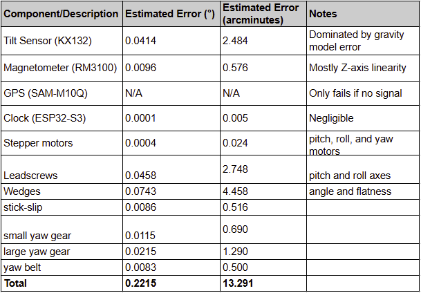
The total is only 13.3 arcminutes, so theoretically we’ll be able to achieve our worst-case accuracy goal!
And this is just the absolute worst-case, assuming every single error source is maxed out. To calculate expected typical error, we use this equation:
Etypical = √(E12 + E22 + … + En2)
In our case, this results in a typical expected error of only 5.1 arcminutes!
We’ll certainly need to test everything to check the assumptions and look for additional error sources, but this is very good news.
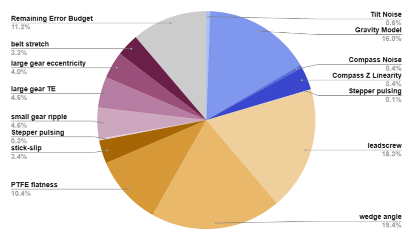
This is also a great guide for where to put effort in the future if we need to eliminate error. Here are our largest error sources and some potential improvements:
Wedge angle - this one will be difficult to physically improve since it’s limited by machining tolerance, but one solution could be adding in a measurement step during assembly and having the actual wedge dimensions be saved within software for error compensation.
Leadscrew - there’s a very easy improvement here, which is just to use a higher precision, more expensive leadscrew. For now, though, if we don’t need to spend more money, we won’t.
Gravity model - there are other more accurate gravity estimation algorithms that I need to look into, but from preliminary searching it seems like they require much more memory than the currently selected ESP32 processor has. I’ll keep digging here.
For the next journal entry I plan on diving into more creative, less mathy stuff. Stay tuned and thanks for reading!