Journal Entry #4: Force Math!
Now that we have a general design to move forward with for the mechanical system, it’s time to figure out the details of how to make that design actually work..
As the title implies, this will be much more math-heavy than previous journal entries. That said, I’ll try to keep it fairly high level, with a focus on concepts instead of equations. This is basically me thinking out loud and making notes for myself, so it’s not the most organized (or easily readable) thing.
This entry will be divided into two main sections: the pitch and roll axes, and the yaw axis. Within each of these, we have two goals. First is to determine the minimum force requirements for our motors so we can choose the correct motor for each axis, and second is to determine the total worst case error for each axis (specifically error caused by the mechanical system).
I’ll split the error calculations into a separate journal entry, so this one will focus solely on force requirements.
Requirements
For a reminder, here are the relevant project requirements from the first journal entry:
Must be able to handle a 20lb telescope
Must be operational on a surface tilted up to 10° from level
Must be usable on tilted ground, but does not need to prevent the telescope from falling on extremely tilted ground
Must have a battery life of at least 4 hours on a full charge
Must fit within a carry-on suitcase
One more stability requirement
One requirement we need to extrapolate from these is the maximum distance the telescope can be from the center of the platform, since this will define the maximum amount of force each individual corner might feel from the telescope. It’ll also define the worst case for how hard the yaw axis has to work to turn the platform if it’s on tilted ground. This math is much easier if we assume every telescope to be perfectly centered by the user, but that simply won’t be the case in real life.
The key to this calculation is figuring out at what point the telescope will cause the platform to tilt and fall over. This happens when the center of gravity of the telescope is placed outside of the area created by the platform’s feet. For example, we’ll be using 3 feet on the platform for stability - as long as the telescope’s center of gravity is directly above the triangle created by these three feet (the “stability triangle”) the whole system will remain stable and upright.
We need to find the point on that triangle closest to the center of the platform - that’ll be the number we’re searching for, called the maximum distance of stability.
This number relies almost entirely upon the overall size of the platform, which is limited in our case by the need to fit inside a carry-on suitcase. The important limit here is the 14 inch maximum suitcase width, which we’ll imagine to give an internal width of 13 inches for safety.
I want the feet of the platform to be entirely underneath the main body of the platform so the telescope weight has a nearly-straight line going down into the ground (for stability). With this in mind there is a spectrum of ways to make the platform fit within this 13” width.
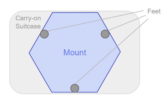
On one side of the spectrum is a hexagonal shaped platform, which would give the most distance from the center to the feet. This distance is (13”)/2 =6.5”.
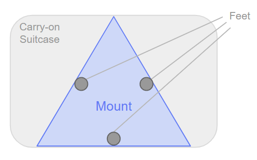
On the other side is a perfect triangle, which would give the least distance from the center to the feet. The center would be (13*(1/3)) =4.33” from the edge of each foot.
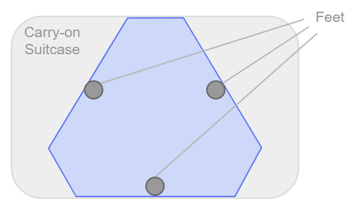
I’m not a fan of either of these extreme shapes for this project, so I’ll go with a mid-range number of 5.5” for the center-to-foot distance. This gives the design a nice semi-hexagonal shape.
So that’s the distance from the center to one of the corners of our “stability triangle” mentioned earlier. To find the maximum distance of stability from this, we can just divide it in half (due to the distance ratios on an equilateral triangle). So the maximum distance of stability is 2.75” when on flat ground!
But wait - what about on tilted ground? It’ll get slightly smaller if the platform is tilted our required maximum of 10°, since the telescope’s center of gravity would now be ‘hanging over’ the bottom edge of the stability triangle at a distance of 2.75”. The new number is pretty easy to find with trigonometry if we assume a conservative platform thickness of 3”: tan(10°) = x/3” where x is the subtracted distance from the previous number. So the maximum distance of stability is 2.22” when on tilted ground!
Pitch and Roll Axes
The pitch and roll axes are the ones that are controlled by a wedge pushed by a leadscrew, so the order of operations needs to go something like this:
Calculate the worst case force pushing down on one corner of the wedge from the telescope. Add pre-load spring force and a healthy margin of safety.
Convert that maximum vertical force into a horizontal force necessary to push the wedge. Add in the friction forces from the top and bottom of the wedge.
Convert this required horizontal force into a torque requirement from the motor turning the lead screw that pushes the wedge.
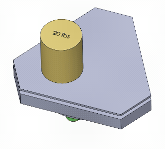
Vertical Force
Based on the 20lb telescope requirement and the maximum distance of stability of 2.75” on flat ground, we find that the worst case force requirement on a single corner is 13.33 lbs. I want a 50% margin of safety on top of this (to account for any unforeseen issues or friction or user mistakes), which coincidentally brings it back up to 20 lbs. I also plan on adding a 5 lb pre-load spring to hold the lifter in place and help with smooth movement, so that’s a total force of 25 lbs or 111 Newtons (N).
Horizontal Force
In an ideal world without any friction, calculating the horizontal force requirement is as easy as finding the wedge’s width:height ratio and dividing the horizontal force by it. I’ve been playing around with a number of wedge ratios in 3D modeling + excel, and have settled on a 3:1 ratio (for 30mm of horizontal movement, it pushes the lifter up 10mm). With this ratio, the theoretical required horizontal force is only 111/3=37 N.
Friction is more complicated to calculate, and is a big design problem to solve. The materials I’m thinking of using are stainless steel for the wedge itself, and PTFE strips attached to the lifter and the base (above and below the wedge for it to slide against). This combination has a relatively low friction, though it’d be significantly lower if the wedge was made of normal steel instead of stainless. The problem then is risk of rust, which isn’t acceptable, so stainless steel is the next best thing.
The key variable for this calculation is the coefficient of friction, which ranges depending a bunch of things like the materials’ surface finishes and flatness. For stainless steel against PTFE, we’ll use a conservative but reasonable coefficient of 0.10.
Using this coefficient plus some fun trigonometry, we get a top-of-wedge friction force of 11.7N and a bottom-of-wedge friction force of 11.1N. Adding this together with the theoretical zero-friction force gives us a total required horizontal force of 59.9 N to sustain and lift the telescope in a worst case scenario.
Torque From Motor
Conversion of this horizontal force requirement into a motor torque requirement depends entirely on the leadscrew we choose. There are three variables from the leadscrew that matter: the diameter (specifically the mean diameter), the lead (how far a nut moves on the screw with one turn) and the coefficient of friction between the nut and the screw.
For simplicity’s sake, I’ve done this calculation using a leadscrew I already have on hand. It’s a TR8 leadscrew (8mm diameter) with a 2mm lead, and it includes a stainless steel screw with a brass nut. A TR8 leadscrew has a mean diameter around 7mm, which is just the average diameter of each screw ‘tooth’, and a conservative coefficient of friction for the leadscrew would be around 0.20.
Based on those numbers, we can find the leadscrew’s overall efficiency. In this case the efficiency ends up being 30.7%, which means only 30.7% of the energy from the motor actually transfers to the wedge. Finishing this calculation, we find that each pitch and roll motor needs a minimum torque of 6.2 Newton-cm to handle the worst case scenario.
Yaw Axis
The yaw axis experiences the most stress when the platform is tilted and the telescope’s center of gravity is at the maximum distance of stability from the center (2.22”). With this worst case scenario in mind, we can calculate a theoretical (frictionless) maximum yaw axis torque requirement of 88.1 N-cm. Adding in friction, assuming a conservative coefficient of friction of 0.20, we can just multiply that torque by 1.20 for a realistic requirement of 106 N-cm. We’ll want a healthy margin of safety on this axis too, so adding in another 50% results in a full requirement of 158.5 N-cm.
This isn’t achievable with small stepper motors, so we’ll need to add a gear or belt system to trade motor speed for additional torque. For example if we use a gear/belt ratio of 12 we’ll only need the yaw motor to output 13.2 N-cm. In a future blog post I’ll be working on actual motor selection, so this final ratio choice will have to wait until then.
Summary of Force Requirements
Low friction is required in all axes - calculations have been done assuming sliding interfaces of PTFE against stainless steel.
Each of the pitch and roll axes needs a motor that can output at least 6.2 N-cm.
The yaw axis requires a motor with a minimum output torque of 13.2N-cm if using a gear/belt ratio of 12