Journal Entry #3: Mechanical Design Overview
In this journal entry I’ll be going over the basic mechanical movement system for the project.
Let’s start high level and work our way down. The goal of the movement system is to rotate the top surface (the platform) in a way that perfectly cancels out the rotation of the earth, so that the platform moves with the night sky.
Theoretically, since the earth is rotating along a single axis at a constant speed, we could get by with only one motor. That’s exactly how traditional equatorial platforms work - they have a single motor moving at a constant speed, which rotates the platform in a cone shape around an axis aligned with earth’s axis of rotation.
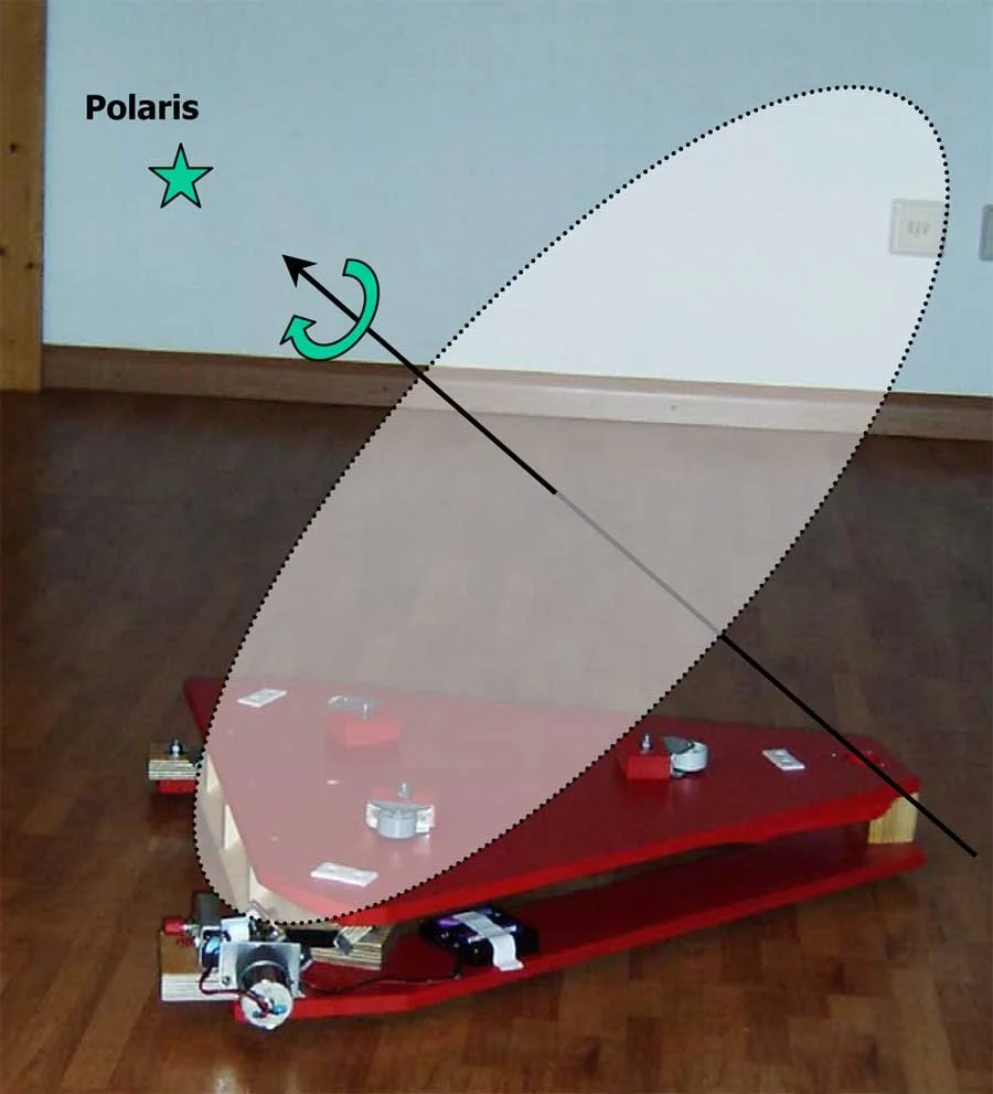
Here’s an example of a traditional equatorial platform, with the axis of rotation overlayed. The rear of the system, shown on the right side of the image, is a pivot point that the top platform rotates around.
Source: Reiner Vogel, www.reinervogel.net
Here’s another example, showing a traditional equatorial platform in motion. The key features are the curved triangular silver parts on the left and right sides of the moving top section (which define the conical curve the platform follows) and the single motor under the right curved piece.
Source : equatorialplatforms.com
There are a few reasons we need more than just a single motor like these platforms have. As I mentioned in my first journal entry, these reasons have to do with the portability requirements I set early on.
Traditional equatorial platforms require manual alignment with celestial north. Since the axis of rotation for the platform isn’t moved by the motor at all, it needs to be set up precisely to match the axis of rotation of the earth.
Traditional equatorial platforms are limited to a small range of latitudes. Keep in mind that the axis of rotation for the platform has to be angled further up the farther from the equator you get in order to stay matched to the earth’s axis. In the 2nd picture above, the curved triangular pieces are what define the conical curve the platform follows and therefore define the angle of the axis of rotation. They are designed for specific latitudes, so if you bring a platform to a different latitude, these triangular pieces have to be swapped out.
Since a <30 second automatic setup is part of the project requirements, neither of these are acceptable. The system needs to be able to automatically align to celestial north and automatically compensate for an arbitrary latitude.
What this means in practice is that we need a full 3-axis motion system. We need a yaw axis to rotate the platform in the horizontal plane, plus a pitch axis and roll axis to rotate it in the two vertical planes.

Designing a 3-Axis Motion System
There are a ton of ways to design a 3-axis motion system, but I’d really like to take inspiration from these traditional equatorial platforms with their flat triangular design.. Theoretically, if we use a triangular platform with a pivot point on one corner, we can place ‘lifters’ on the other two corners which can be our pitch and roll axes. So movement on the pitch axis would be lifting one corner of the triangular platform up and down to tilt it one way, and movement on the roll axis would be lifting another corner, tilting it in a different direction. The third corner would be locked in place, but free to rotate and tilt.
The yaw axis would still be very simple, rotating the entire assembly along the horizontal plane.
In addition to keeping a lot of the style of traditional equatorial platforms, this design has some serious advantages for stability and accuracy.
Pitch and Roll Axes
If positioned correctly, the lifters making up the pitch and roll axes don’t need to move much. We have a requirement of 30 minutes of uninterrupted star-targeting, which we should be able to achieve with less than 10mm of vertical movement based on some very rough calculations.
(The actual platform will be much larger than this small 3D printed model)
That said, we don’t want to minimize movement too much. If it’s moving 10mm over a half hour, that’s a speed of around 0.005mm/second. And remember, to minimize tracking errors we need the movement to be extremely smooth, which can be difficult at such slow speeds.
We also need to remember that this system needs to be super stable to avoid vibrations in the telescope/camera sitting on the platform.
With these requirements in mind I played around with a few ideas for the pitch and yaw axes, and settled on a design I want to tentatively move forward with.
The idea is a machined metal wedge pushed by a high-quality lead screw which is rotated by a stepper motor.
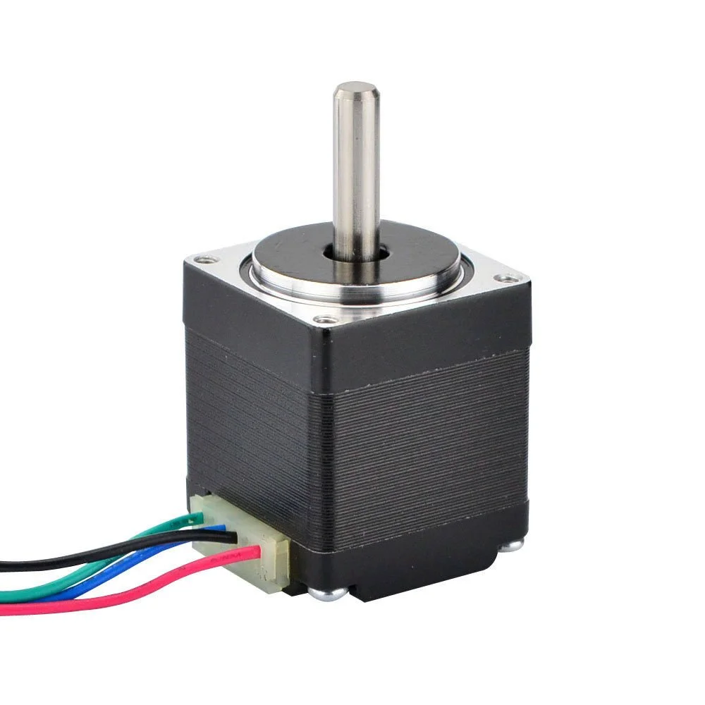
Stepper Motors
I’ll explain backwards starting from the motor. A stepper motor is a type of motor that is essentially controlled using pulses of electricity, with each pulse moving the motor one ‘step’. A step is usually 1/200 of a rotation, but with modern control systems it can be more along the lines of 1/50,000 of a rotation. They are excellent at keeping precise positions, and excel in slow speeds.
Stepper motors are very accurate at low speeds, powerful enough to meet our strength goals, and come in a variety of widely-available sizes.
Lead Screws
The pitch or roll motor would be turning a high-quality lead screw, which is a category of precision screws that convert rotational motion (like from a motor) into axial motion (push-pull movement).

Stepper motors and lead screws are the standard way to design high-precision movement systems; it’s common to order stepper motors with built-in lead screws like this.
Wedge Design
The lead screw converts the rotation of the stepper motor into push-pull movement of a metal wedge. The wedge, in turn, slides under the ‘lifter’ which makes the platform move up or down.
The wedge and lifter need to be machined out of metal for precision, and likely also need low-friction PTFE layers on each sliding interface to minimize stick-slip friction at low speeds.
Here’s a basic model of the system, using an off-the-shelf stepper motor and leadscrew to push a 3D printed wedge under the red lifter.
Error Sources
There are multiple potential sources for error in this design, which I’ll spend time calculating in a future journal entry:
Stepper motor pulsing frequency and smoothness
Leadscrew movement accuracy
Wedge surface smoothness and flatness
Wedge angle accuracy
Sliding friction of wedge and lifter
Yaw Axis
The yaw axis is much simpler than pitch and roll, since we’ll just need to translate the rotational motion of a stepper motor into the rotational motion of the platform.
As I mentioned earlier, modern stepper motor controllers can give motors up to around 50,000 steps per revolution, which is an accuracy of 0.0072 degrees. That means even if we simply connected a stepper motor directly to the rotating yaw axis, the accuracy would probably be sufficient. however, keep in mind the yaw axis needs to be able to reliably rotate the platform with a full 20lb telescope on top. Therefore, we might need some gearing between the motor and the yaw axis to add strength. I’ll do this full analysis in my next journal entry, but I don’t anticipate significant issues.
Error Sources
The simpler mechanical system for this axis means fewer potential sources of error:
Stepper motor pulsing frequency and smoothness
Gear imperfections, if we use gearing to add strength
Sliding friction between the rotating section and the stationary section of the system
In the next journal entry I’ll be diving into the math behind this motion system. Based on the project requirements we’ll need to calculate how strong the motors need to be and how much new error might be introduced, and then use this info to select motors, motor controllers, and a battery for the system.
Thanks for reading!