Journal Entry #2: Choosing Sensors
Over the past few weeks, I’ve been deep in sensor selection and trying to figure out how to compensate for all the potential sources of error in the system. In my last journal entry, I mentioned that the Universal Polar Mount theoretically needs just three things to calibrate itself:
The tilt of the platform
Compass heading
GPS coordinates
In this post, I’ll dig deeper into the components that provide those three inputs, and how I plan to minimize the errors they introduce. I also realized I might need a fairly accurate clock since even small amounts of drift could impact sky tracking over time, so I’ll include a quick section on that too.
Error Budget
The key goal here is to keep the total error across the entire system as small as possible. In my first post, I set a target of staying within 15 arcminutes (0.25°) of the true polar alignment. That means every source of error (sensors, motors, mechanical flex, everything) has to stay under that combined limit.
If we don’t meet this error budget, we risk an issue called star trailing when taking photos of the night sky:
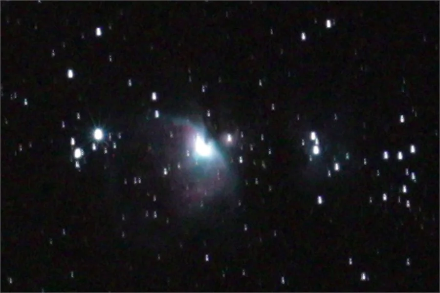
Notice how each of the stars appear as a small line instead of a point, and the entire image is somewhat blurry. This is an example of star trailing.
Image source: Jerry Lodriguss, “Diagnosing Trailed Stars” www.astropix.com/html/astrophotography/diagnosing_trailed_stars.html
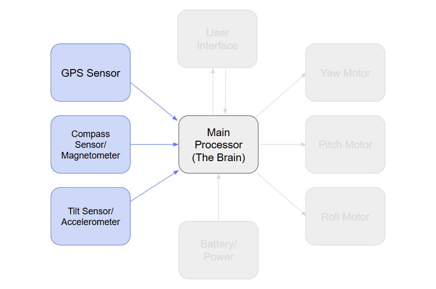
Here are the main expected contributors to the overall error budget for this project:
The compass (magnetometer)
The tilt sensor (accelerometer)
Internal clock drift
Magnetic declination accuracy
Stepper motor precision (pulse timing and control)
Mechanical alignment (pitch, roll, yaw)
Bending or flex in the physical frame
For now, I’m focusing on just the sensors (the compass and tilt sensor in particular) since they’re critical for calculating orientation.
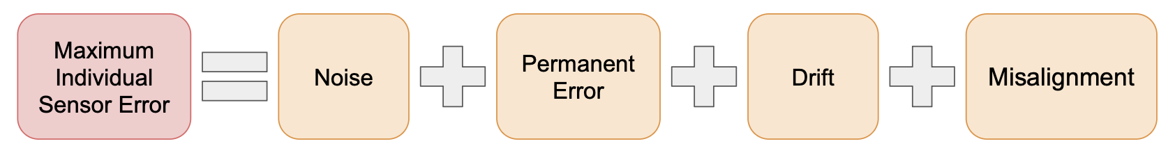
Sensor Error Types
Both the compass and tilt sensors I’m using are 3-axis sensors, basically three separate sensors per chip, each offset by 90°. The benefit of 3 axes per sensor is we can combine the data to find the exact direction of gravity and earth’s magnetic field in 3D space. However, it means I’ll be dealing with a total of six independent axes, and each one can introduce its own types of error. These fall into a few key categories:
Random noise
Every sensor measurement has a little bit of built-in randomness, known as noise. Luckily, this is the easiest kind of error to reduce; just take more readings and average them. The improvement follows a square root rule: take 1000 readings, and the noise decreases by a factor of √1000 = 31.6.
Correction required: more readings
Correction difficulty: easy
Permanent Sensor Error
Each axis can also have small permanent errors from the manufacturing process. These are usually split into:
Bias – a constant offset (e.g., actual value + error)
Gain error – a scaling mismatch (e.g., actual value × error)
Some higher-end sensors come factory-calibrated to correct these, but that’s not likely at my price point. Fortunately, if the sensor is stable over time, I can measure and compensate for these permanent errors myself with a one-time calibration during assembly.
Correction required: one-time manufacturing calibration
Correction difficulty: tricky to figure out the math, but easy to apply and repeat once set up
Drift Over Time or Temperature
These same errors can also drift (change) over time or as the sensor heats up or cools down. Typically temperature-based drift is much larger than time-based drift, and that’s relevant to this project because the system might be used in weather anywhere from 10°F to 90°F and beyond. In some cases, this drift is big enough to seriously affect performance. Some sensors have built-in temperature compensation, which might be worth the extra cost.
There’s a partial workaround: do a basic calibration of the sensors every time the system starts up, not just once during manufacturing. By using a motor to rotate the sensor 180° around the Z axis, I can take two readings that should be exact opposites (and therefore equal in strength). If they’re not exactly equal in strength, the difference is the bias! This is only true for X and Y though, not for Z, since Z doesn’t change when rotating around itself. That’s a limitation I’ll need to live with unless I splurge on a higher-end sensor.
Correction required: startup calibration for XY + a stable sensor for Z
Correction difficulty: easy
Misalignment of Axes
Ideally, each axis would be exactly 90° from the others, and the sensors would be mounted perfectly level on the PCB. In reality, neither of those things will be true. Even high-end sensors can have a few degrees of internal misalignment, and PCB placement errors add more.
Luckily, this error is fixed (it doesn’t change over time) so I can measure and fully correct for it just once during manufacturing.
Correction required: one-time manufacturing calibration
Correction difficulty: tough math, but once it’s done, it’s done
With all that in mind, let’s take a look at some potential sensors and calculate how much worst-case error they could add to our system.
Tilt Sensor/Accelerometer
The sensor I’m currently considering is the KX132 by Rohm Semiconductor. It costs between $6 and $9 depending on quantity ordered.
Random noise
Its datasheet lists a typical noise error of 130 µg/√Hz (these types of sensors use a base unit of gravities ‘g’. Earth’s gravity is simply 1.0g). With a reading frequency of about 33.3Hz (enough to get 1000 readings in 30 seconds), the sensor would have a noise of 750 µg.
Over 1,000 measurements, this noise is reduced by about 31.6X, bringing the noise down to 23.7 µg.
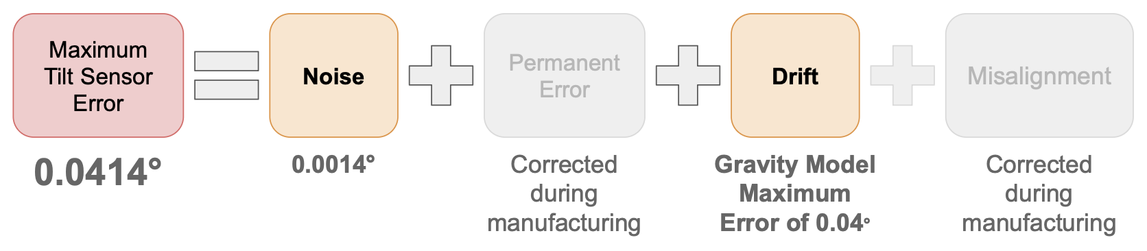
To convert that to tilt error in degrees, we use the formula: arcsin(error/gravity). The result is 0.0000237 radians, or 0.0014° noise error.
Permanent Sensor Error
This data sheet specifies a bias of ±90mg, which is huge (9% of the earth’s gravity). Luckily, as mentioned earlier, this error is stable so we can fully correct it with a one-time calibration during manufacturing.
Drift Over Time or Temperature
This sensor doesn’t specify time-based drift in its datasheet, but it does specify temperature-based drift of 0.25mg/ºC. If we do a calibration upon startup, this error will be eliminated for the X and Y axes but not for the Z. There might be a workaround, though, to eliminate this Z axis drift on the tilt sensor specifically.
The trick is, because we know Earth’s gravity is a constant 1 g, we can calculate the expected Z-axis value using just X and Y. That lets us indirectly “fix” Z too. This means we can ignore the sensor’s Z axis measurements completely.
One catch, though: weirdly, gravity isn’t exactly the same everywhere on the planet. But we can use the WGS-84 gravity model, which estimates local gravity based on GPS coordinates. The model’s worst-case error is about 0.05%, or 0.005 m/s², which translates to about 0.04° of tilt error at a worst-case 15° angle.
That error isn’t correctable without a more stable sensor, but I’m okay with that for now.
Summary of Tilt Sensor Error
Compass Heading Sensor/Magnetometer
Just like with the tilt sensor, I’ll be taking 1,000 readings with the compass sensor to minimize noise. The magnetometer I’m looking at is the RM3100 from PNI Sensor. It costs $25/sensor currently.
Random noise
Its data sheet lists a typical noise of 30 nT (these types of sensors often use a base unit of teslas ‘T’. For reference, the earth’s magnetic field is typically around 50 microteslas).
Over 1,000 measurements, this noise is reduced by about 31.6X, bringing the RMS noise down to 0.95 nT.
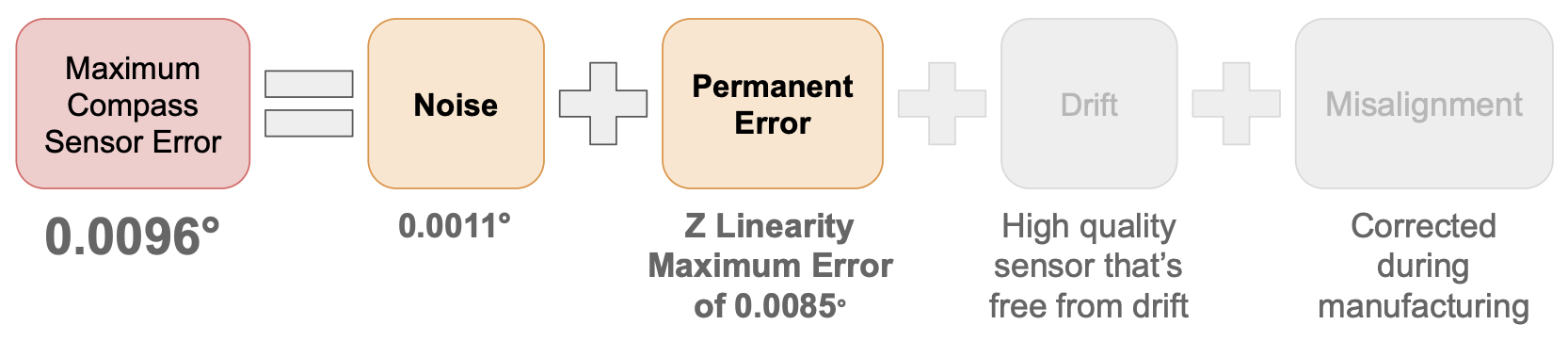
To convert that to heading error in degrees, we use the formula: arcsin(error/magnetic field strength). With earth’s magnetic field strength of 50µT the result is 0.000019 radians, or 0.0011° noise error.
Permanent Sensor Error
The data sheet lists a linearity error of 0.5%. This means the sensor’s scale factor (gain) isn’t perfectly consistent- it might give a measurement slightly too big or small.
For our use case, where Earth’s magnetic field is around 50 µT, that 0.5% error could cause a 0.25 µT shift in the reported value. If this happens in the uncalibrated Z-axis (which we can’t easily correct), it can skew the tilt-corrected heading by up to 0.0085° in worst-case scenarios. Not massive, but a significant part of the total error so far.
Drift Over Time or Temperature
The RM3100 is the industry standard due to its stability; the datasheet notes the sensor is “inherently free of offset drift” and temperature-stable. That’s one big source of error we can cross off the list.
Summary of Compass Sensor Error
GPS Sensor
This one’s pretty straightforward. I’m using the SAM-M10Q made by u-blox, which gives me:
Latitude (for alignment with Earth’s rotation axis)
Longitude and altitude (for computing magnetic declination)
Satellite lock-on time under 30 seconds
Built-in antenna
Easy integration with my ESP32-based board
There’s not much that can go wrong here unless the GPS doesn’t get a signal. If that happens, the mount simply won’t calibrate and I can show the user a clear warning.
Clock Module
Before exploring additional clock modules I first considered using the internal clock of the ESP32-S3, the main processor for this project. According to its datasheet, the timer accuracy is ±10ppm, or ±0.01ms.
Over 30 minutes, that means a total drift of 18ms. Since the night sky moves at about 0.0042° per second (360°/86400 seconds), an 18ms drift results in a very small 0.000075° error.
This error is negligible, so no external clock module is needed!
Total Error So Far: 3.1 arcminutes


The largest error source by far is the WGS-84 gravity model we’re using to calculate the tilt. If we end up needing to minimize this error later we may be able to switch to a more accurate model, but at the cost of increased memory usage from our main ESP32 processor. We’ll cross that bridge when we come to it.
Overall, this is in a really good place - testing will still be required to validate these numbers, but so far we’ve only used 20% of the error budget!
What’s Next?
I’ve ordered the sensors and will begin testing once they arrive. My first goal is to try the 1,000-reading rotation system for the tilt and compass sensors, but before that, I need to develop a basic motion system.
This will involve selecting motors and motor controllers. It’ll require a bit of math to convert telescope weight and battery life into the necessary motor specs.
Even before I get into that, though, I need to actually design the basic mechanical movement system for the Universal Polar Mount. This will give me a solid foundation for the motor calculations, and it’ll be the focus of my next journal entry.
Thanks for reading!