Journal Entry 10: A Few Changes
Product design is an iterative process. It always involves hurdles and fixes and compromises and backtracking, and this project is no different. In my journal entries I usually try to smooth things out a bit so they aren’t novels, which means leaving out a lot of trial and error and focusing on the interesting parts or the lessons learned.
Over the past few weeks, though, I’ve hit two roadblocks that require more substantial changes to the product and invalidate some of the work done in the past entries. Because of that, an explanation is called for.
The big one
As we’ve talked about previously, the product is essentially divided into two sections: inputs and outputs. The inputs are how we determine where the platform is in space and how it relates to the earth’s axis, and the outputs are the motor movement and mechanical system.
The biggest change is with the inputs. So far we’ve designed the whole system to use a stack of sensors to find the earth’s polar axis:
We use an accelerometer to determine the platform’s tilt on the ground
A magnetometer to find the earth’s magnetic field and the direction of magnetic north
A GPS sensor to get latitude and longitude, which we use to look up the local magnetic declination (which lets us correct large imperfections in the direction of magnetic north.
All of these individual sensors add sources of error to the system, which stack on top of each other. The goal is to minimize them enough that we stay under our error budget of 15 arc minutes, which as I’ve calculated previously, we’ve achieved.
The problem is, my math was wrong. Or not really my math, but my assumption that when we ‘look up’ the local magnetic declination, that gives a perfect correction for the magnetometer’s north direction. it doesn’t, for two reasons.
One is that the best lookup tables available are only accurate to 30 arc minutes, which I am kicking myself for not seeing on NOAA’s website earlier:
“In general, the present day field models such as the IGRF and World Magnetic Model (WMM) are accurate to within 30 minutes of arc for D and I and about 200 nanoTesla for the intensity elements.”
If that wasn’t enough, this also pushed me towards discovering even larger issue with the magnetometer’s calculated north direction. We can account for any hard or soft iron that spins with the magnetic sensor in the platform (like the metal platform enclosure or the magnets in the motors) but we can’t account for anything that is outside the platform. So if there’s a car nearby or even certain types of rocks underground, they’ll distort the earths magnetic field enough to cause problems.
What I’m getting at is the sensor stack concept is not a reliable way to find the earth’s polar axis accurately. In fact, nothing that includes magnetism will be a reliable way to find it, given the portability requirements of this project.
If we think about it, there’s really only two ways we define ‘North’. One is magnetic north (where compasses generally point), and one is true/celestial north. If we disregard finding magnetic north as a path, we have to focus on true/celestial north (which is what we’re after anyway, at the end of the day). And the only good reference for that is looking at the stars in the sky.
We need to add a camera to the system.
I noted in one of the earlier entries that we might need a camera for the last little bit of accuracy on top of the other sensors, but I think we actually need to use it for the entire sensing solution. The good news is there are already programs available (called plate solvers) that can use photos of the night sky and calculate position from them (namely tetra3) but the bad news is taking those photos of the night sky reliably is no simple task, especially at a low cost.
Expect a number of blog posts going down this path in the near future. After my initial disappointment with wasted work, I’ve actually become really excited about this change. It’ll be much more accurate and I’ve been interested in learning more about the technical side of astrophotography for a while.
After some initial learning, I’m leaning towards using one of Sony’s STARVIS camera modules. They’re cheap, widely available (depending on the model) and very well suited for this purpose.
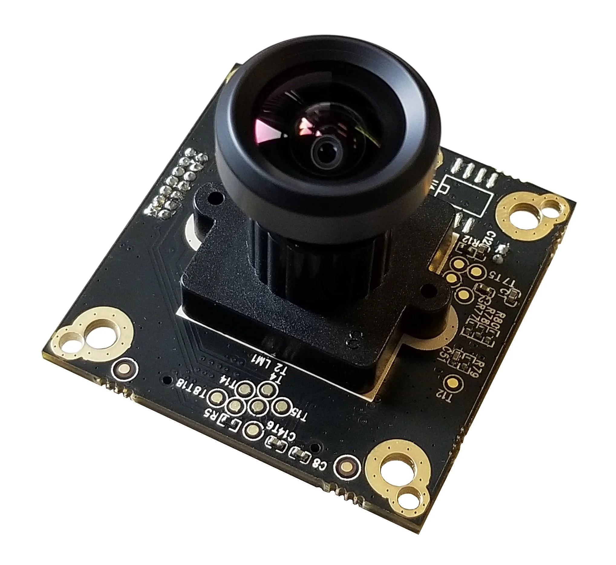
IMX335 STARVIS module
source: www.leopardimaging.com
Note that I’ll probably still keep the accelerometer and magnetometer (though maybe cheaper versions) as a fallback if the plate solving fails or if there are camera issues. Plus, I have some ideas for using those sensors to correct the platform if someone accidentally kicks or nudges it out of alignment.
The smaller problem
The other problem deals with the mechanical system, and it’s also because of some incorrect math I did early on. One of the project requirements is the ability to stay on-target for at least 30 minutes uninterrupted. My initial math indicated that a lifter height of around 10mm would be sufficient, given the expected space between the lifters. When I looked back at this math last week I found some glaring issues and calculated that the real lifter height needs to be closer to 30mm to have a minimum 30 minute tracking time anywhere on earth.
Seems like a simple fix - can’t we just make the wedge design 3X taller? While that’s correct, it’d also result in the height of the platform increasing by 3X. At that height telescope stability becomes a larger concern, plus aesthetically I just prefer the look of a thin platform. So that’s a no-go.
What I did find as a potential solution is called a ‘non-captive stepper motor’. Instead of the motor being attached to the end of a leadscrew like the previous wedge design (with the wedge acting as a nut on the leadscrew so it can move back and forth).
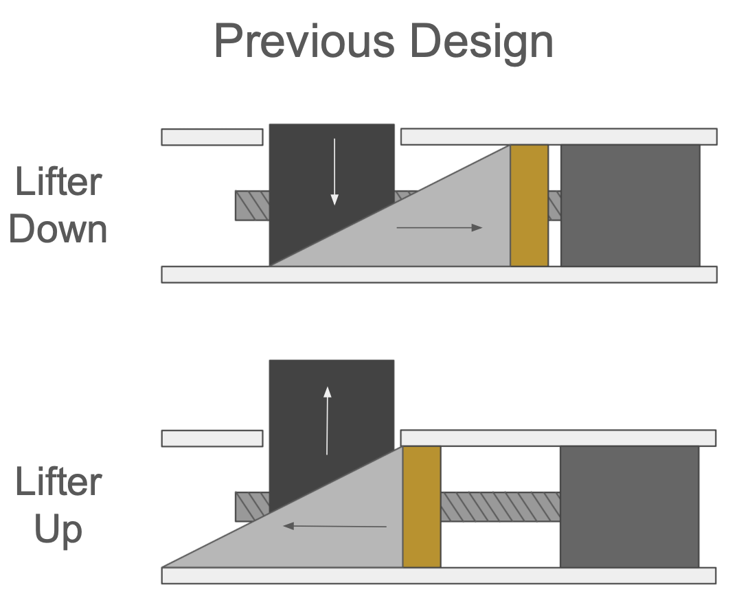
The ‘non-captive’ version is a variation of this where the leadscrew doesn’t turn at all, but the inside of the motor turns like a nut. That makes the leadscrew itself move back and forth with the motor staying still.
If we use a similar motor size to the yaw axis, we can turn the lifter motors vertically and have the lifter surfaces be directly attached to the top of the leadscrews. This should use a similar amount of power to the previous design, and would actually eliminate a bunch of mechanical parts (and therefore failure points).
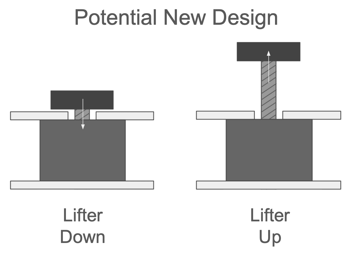
Of course it’s disappointing to have delays in the project and to redo a lot of work. But the ‘wasted’ work that’s already been finished taught me a lot, much of which I’m confident will still find its way into the final product.
These changes are going to be great for the design. They’ll simplify the mechanical side of things tremendously and make the tracking much more accurate. The camera and plate solving will take more development time to get right, but I’m excited to get started.
These won’t be the last issues, and this probably won’t even be the last time I need to backtrack on something important. It’s all part of the process, though.
Thanks for reading!