Journal Entry #9: First Prototype!
The first journal entries were mostly about calculating and minimizing the theoretical error of the tracking system. We based all the math on specs for the sensors and motors and came up with a ‘worst case’ error that was within the project’s requirements. However, theory and math can only get us so far.
We need to test the system in the real world. We need to see how it performs and what unexpected issues appear. The first step is designing a prototype.
Requirements
The prototype doesn’t need to be polished or even look remotely like the final product. It just needs to include the sensors we want to test + the motor drivers. The priority right now is testing and confirming everything can connect and talk to each other.
Specifically, here are the requirements for the first prototype:
Electrical board:
ESP32-S3 microcontroller (the brain of the system)
3X motor drivers (pitch, roll, and yaw)
KX132 tilt sensor
RM3100 magnetometer
SAM-M10Q GPS module
Light sensor (for user interface stuff)
additional I2C connections to add other sensors if needed
Mechanical Frame
Able to spin the electrical board steadily and parallel to the ground plane
Able to move basic 3D printed lifters vertically using a simple wedge design
The motors should be as far from the RM3100 magnetometer as possible
Motor Drivers
I decided to go with TMC2209 stepper motor drivers. I thought about doing a whole explanation of how these were chosen, and what they were compared against, but they were actually a much simpler choice than I anticipated. They can operate on both the final 12V voltage as well as the 5V used in this prototype, they have some really great features to minimize noise and power usage, and (most importantly) they are ubiquitous + cheap due to their common usage in 3D printers.
We control these stepper drivers, and in turn they control the stepper motors themselves, by sending the drivers three separate signals from the microcontroller (the brain). Those signals are enable, direction, and step. Each signal is one wire (also called a ‘pin’), and the wire’s voltage can either be high (electricity is being sent) or low (no electricity is being sent).
The enable signal is simply turning the motor on (low signal) or off (high signal). I know the signal levels seem backwards for on/off, but that’s just how the driver was designed.
The direction signal is similar - the high signal prepares to turn the motor one way (CW or CCW depending on how the motor is wired) and the low signal prepares it to turn the opposite way.
The step signal is a bit more complicated. This is what actually turns the motor, but remember that stepper motors move in small increments (steps). Instead of a constant high or low signal, the step signal receives pulses of high voltage. Every time it sees the signal wire go from high→low, it moves the motor one step.
So to actually turn the motor, we first switch the motor on by setting the enable pin low. We then decide what direction we’ll be turning and set the direction pin high/low, and then we start sending the step pin pulses of high then low signals. The speed of these pulses controls the speed of the motor - if we send 200 pulses/second the motor would spin 1 rotation/second, and if we send 2000 pulses/second it’ll spin 10 rotations/second.
Designing the Prototype’s Electronics Board
Let me start off by saying I’m not an electrical engineer. I know the fundamentals, but designing custom circuit boards has always just been a fun challenge. I’ve been fortunate to have very smart electrical engineer friends who have given me tips and let me examine their designs, but please have mercy if you’re an experienced PCB designer looking at this work.
Luckily, all of the parts going on this board have ‘breakout boards’, meaning I can just buy an off-the-shelf version of the part that already has the majority of its circuit attached. For example, here’s the GPS breakout board:
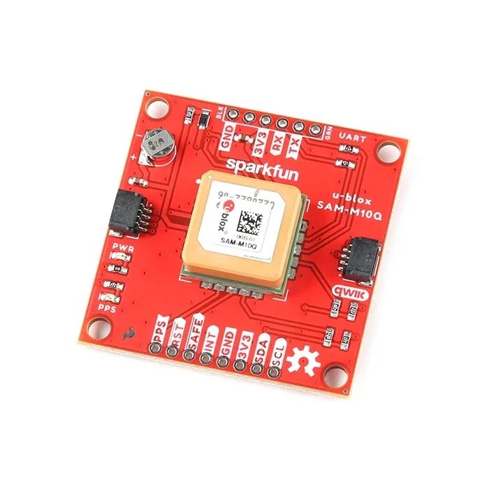
The SAM-M10Q GPS sensor itself is the big tan part in the middle of the board. Everything else is necessary or helpful for the sensor to function correctly, and for the prototype it’s convenient to purchase pre-built like this.
Here’s what the design file of the prototype board looks like:
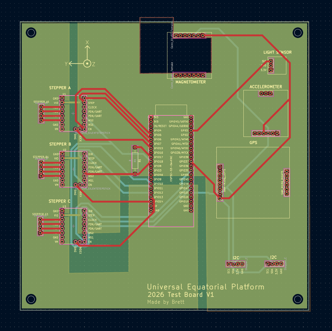
There’s a lot going on here, but it’d be 10X worse without the breakout boards. Before we move on it’s worth a quick overview of what these boards are and how they work.
When designing a circuit, the simplest and quickest way to connect everything is with physical wires. You can buy super cheap wires and connect them directly to breakout boards. However, in a system like this there’d be a lot of wires to keep track of and everything would get super messy and confusing.
The next best thing is this. It’s an all-in-one custom Printed Circuit Board (PCB). In a specialized software (I use Kicad because it’s good and free) you lay out all the parts of your circuit, assign names and values to every connection on them, and then the software guides you in ‘connecting the dots’ and creating printed wires.
These PCBs are manufactured in layers, most commonly with four layers of copper available to be turned into internal wires. Between each layer is a barrier, which is also on the top and bottom of the board. The top and bottom can also be painted with labels and graphics, called ‘sink screening’.
The point is that instead of having a mess of confusing wires, you have a single board that already includes all the wires and connections in a robust package. The downside is that if you get something small wrong in the design you might need to wait to have another board manufactured.
Some things to look at in this design:
The yellow lines are labels that are painted (sink screened) on top of the board
The red lines and light blue lines are ‘traces’ or wires inside the board itself. I used two of the four available copper layers for these wires, and the other two for power and ground connections.
The yellowish green areas are the copper layer for power - there are two sections, one for 3.3V power (for the sensors) and one for 5V power (for the motors)
The bluish green area is the copper layer for ground connections (zero volts, also called the power return path). The ground connection covers almost the entire layer, but it’s blocked visually by the power layer.
The ESP32 microcontroller is in the center of the board, with a small resistor next to it which will help control how it communicates with the stepper drivers.
The four sensors are on the top and right side of the board
The I2C connectors are in the bottom right corner. Many sensors and parts use I2C (Inter-Integrated Circuit) communication to talk to each other, so this might be helpful if we need to add other things.
There are four mounting holes, one in each corner.
One mistake I made in the design that I’m now kicking myself for is I didn’t fill in the two wire layers with what are called ‘ground pours’. After all the wires are designed, best practice is to fill the rest of the layer with copper and connect it to the ground layer. We’ll have to see if it affects the actual functionality.
Prototype Mechanical System
Yaw
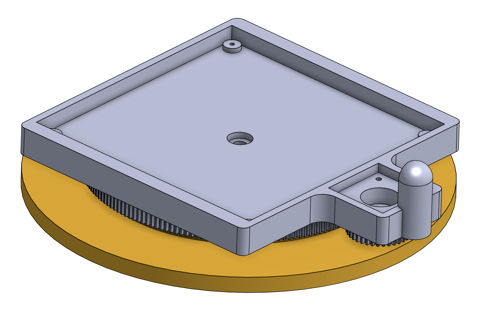
As calculated earlier, we’ll use a gear/belt ratio of 12:1 in the final design to strengthen the yaw axis. For now we don’t need that strength, so we can get by with a simpler ratio of 5:1 that we can make with 3D printed gears.
The mechanical system can then be fairly simple. We need a mounting plate that the electronics board and motor can be attached to, a base that spins underneath the mounting plate, and a gear for the motor that meshes with a 5X larger gear on the base.
To align everything and make sure it rotates correctly, we’ll attach the mounting plate to the base with a small axle and bearing. Between them will be low-friction tape to ensure smooth motion.
Pitch + Roll Lifters
For the lifters, we’ll use the simple wedge design powered by a stepper motor and leadscrew. This only needs to move 10mm vertically, and we’re not worried about friction or efficiency in this prototype. We just want it to move.
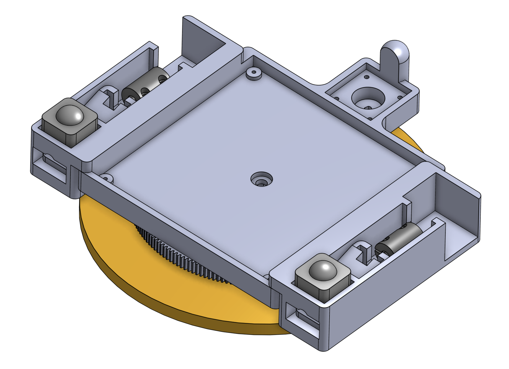
The parts were all 3D printed and came together easily. I did forget to add bolt holes between the yaw section and the two side lifter sections, but glue is sufficient for the prototype. Now all we need is the circuit board.
MECHANICAL PRINT PICS HERE
Receiving and Testing the PCB
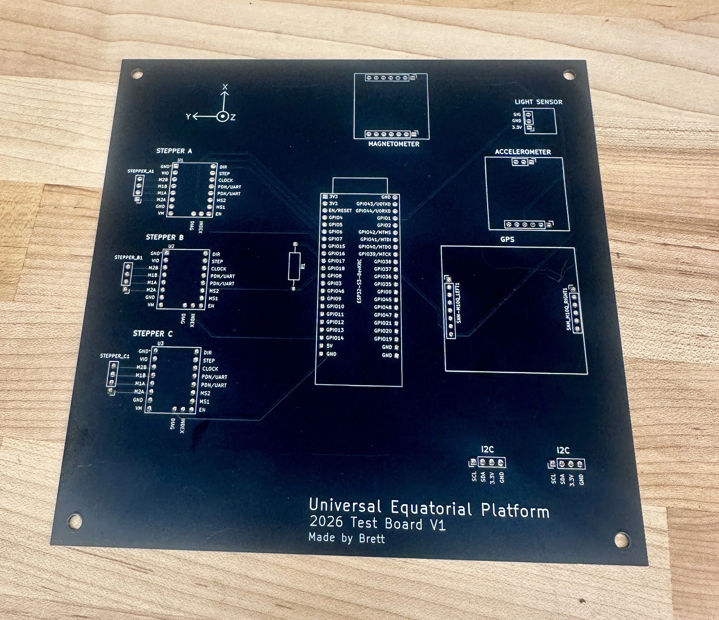
It looks good and it’s super satisfying to see the design in real life, but we won’t know if everything was designed correctly until we start testing.
Libraries
For programming I’m using Arduino, and each of the parts has a pre-written ‘library’ in Arduino that can translate simple code into commands. These libraries are sometimes written by the sensor manufacturer or reseller, but sometimes they’re written and shared by generous makers or community members.
For the magnetometer using this library written by hnguy169: https://github.com/hnguy169/RM3100-Arduino
The accelerometer uses this library from the breakout board’s manufacturer, Sparkfun: https://github.com/sparkfun/SparkFun_KX13X_Arduino_Library
The GPS module also uses Sparkfun’s library: https://github.com/sparkfun/SparkFun_u-blox_GNSS_v3
Finally, the stepper drivers use the TMCstepper library created by teemuatlut: https://github.com/teemuatlut/TMCStepper
Sensors
The beauty of using pre-built breakout boards and matching libraries is that, if everything is connected correctly, things just work.
In this case, I got lucky and didn’t make any mistakes in my PCB design. With a very basic sketch I got the light sensor, accelerometer and magnetometer working!

The light level ranges from 0-255 depending on how dark the area is, and I could easily get it to 255 using my phone’s flashlight. Gravity was mostly pointing down in the Z direction, as expected, as was the magnetic field (In the northern hemisphere, earth’s magnetic field points down into the ground at an angle).
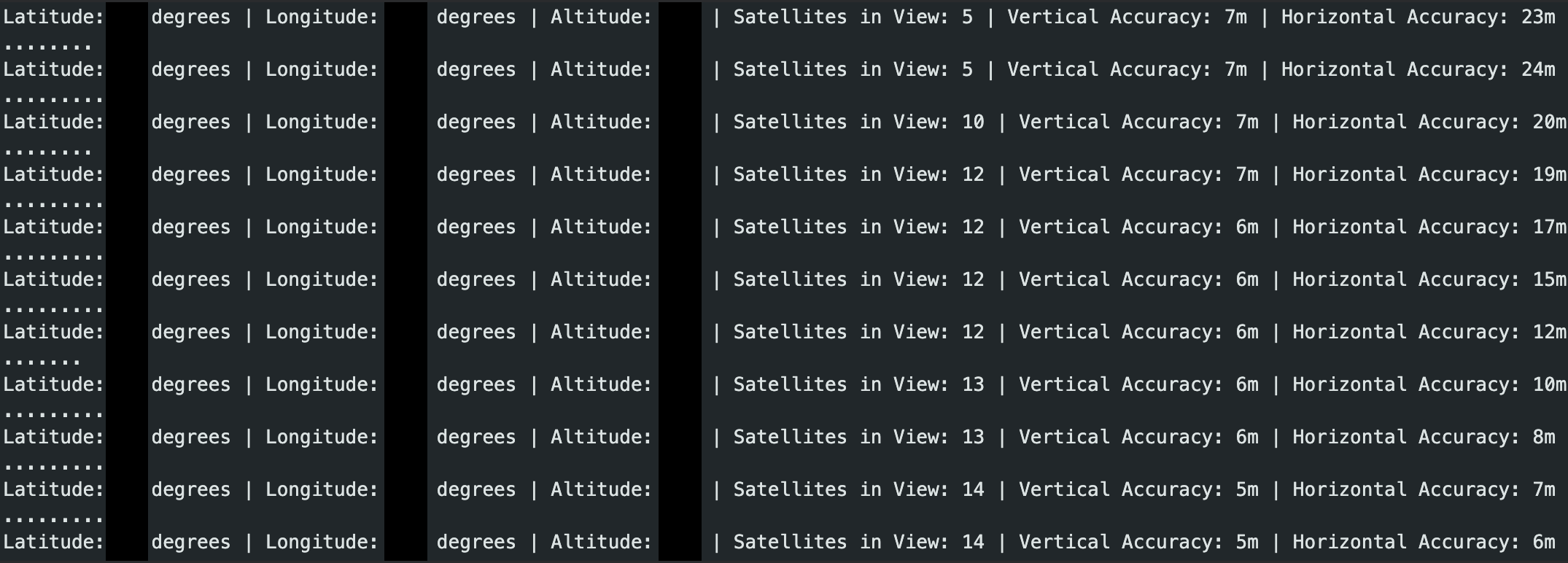
GPS was equally simple to set up, but I had to make sure the board was outside with a clear view of the sky. It’s cool to watch as it slowly acquires signal from more and more satellites.
Mechanical Testing
The board fit into the 3D prints flawlessly, and all that was left was plugging in the motors. The programming was a bit more involved than the sensors, even with the TMCStepper library, but we have movement!
The motors are all running on 5 Volts right now and they can’t move very fast without losing torque, but once we increase to 12V (or maybe even 24V depending on the impacts to battery life) the speed ceiling will go up significantly. the system will usually be moving so slowly this doesn’t matter, but for system startup or end-of-motion resets, quick motion is a nice quality-of-life feature.
Everything was a success with the first prototype! Next I’ll be working on the math behind the sky-tracking movements and testing out some actual motion profiles.
Thanks for reading!